AVR Assembler Help
Welcome to the ATMEL AVR Assembler.
Please select between the following Help items:
The Assembler is also supplied in a MS-DOS command line version. A description
of how to use the Command line Assembler is included in this help file.
General information
The Assembler translates assembly source code into object code. The generated
object code can be used as input to a simulator such as the ATMEL AVR Simulator
or an emulator such as the ATMEL AVR In-Circuit Emulator. The Assembler
also generates a PROMable code which can be programmed directly into the
program memory of an AVR microcontroller
The Assembler generates fixed code allocations, consequently no linking
is necessary.
The Assembler runs under Microsoft Windows 3.11, Microsoft Windows95
and Microsoft Windows NT. In addition, there is an MS-DOS command line
version.
The instruction set of the AVR family of microcontrollers is only briefly
described, refer to the AVR Data Book in order to get more detailed knowledge
of the instruction set for the different microcontrollers.
Assembler source
The Assembler works on source files containing instruction mnemonics, labels
and directives. The instruction mnemonics and the directives often take
operands.
Code lines should be limited to 120 characters.
Every input line can be preceded by a label, which is an alphanumeric
string terminated by a colon. Labels are used as targets for jump and branch
instructions and as variable names in Program memory and RAM.
An input line may take one of the four following forms:
[label:] directive [operands] [Comment]
[label:] instruction [operands] [Comment]
Comment
Empty line
A comment has the following form:
; [Text]
Items placed in braces are optional. The text between the comment-delimiter
(;) and the end of line (EOL) is ignored by the Assembler. Labels, instructions
and directives are described in more detail later.
Examples:
label: .EQU var1=100 ; Set var1
to 100 (Directive)
.EQU
var2=200 ; Set var2 to 200
test: rjmp test
; Infinite loop (Instruction)
; Pure comment line
; Another comment line
Note that there are no restrictions with respect to column placement of
labels, directives, comments or instructions.
Instruction mnemonics
The Assembler accepts mnemonic instructions from the instruction set. A
summary of the instruction set mnemonics and their parameters is given
here. For a detailed description of the Instruction set, refer to the AVR
Data Book.
Arithmetic and Logic Instructions
| Mnemonic |
Operands |
Description |
Operation |
Flags |
Cycles |
| ADD |
Rd,Rr |
Add without Carry |
Rd = Rd + Rr |
Z,C,N,V,H,S |
1 |
| ADC |
Rd,Rr |
Add with Carry |
Rd = Rd + Rr + C |
Z,C,N,V,H,S |
1 |
| SUB |
Rd,Rr |
Subtract without Carry |
Rd = Rd - Rr |
Z,C,N,V,H,S |
1 |
| SUBI |
Rd,K8 |
Subtract Immediate |
Rd = Rd - K8 |
Z,C,N,V,H,S |
1 |
| SBC |
Rd,Rr |
Subtract with Carry |
Rd = Rd - Rr - C |
Z,C,N,V,H,S |
1 |
| SBCI |
Rd,K8 |
Subtract with Carry Immedtiate |
Rd = Rd - K8 - C |
Z,C,N,V,H,S |
1 |
| AND |
Rd,Rr |
Logical AND |
Rd = Rd · Rr |
Z,N,V,S |
1 |
| ANDI |
Rd,K8 |
Logical AND with Immediate |
Rd = Rd · K8 |
Z,N,V,S |
1 |
| OR |
Rd,Rr |
Logical OR |
Rd = Rd V Rr |
Z,N,V,S |
1 |
| ORI |
Rd,K8 |
Logical OR with Immediate |
Rd = Rd V K8 |
Z,N,V,S |
1 |
| EOR |
Rd,Rr |
Logical Exclusive OR |
Rd = Rd EOR Rr |
Z,N,V,S |
1 |
| COM |
Rd |
One's Complement |
Rd = $FF - Rd |
Z,C,N,V,S |
1 |
| NEG |
Rd |
Two's Complement |
Rd = $00 - Rd |
Z,C,N,V,H,S |
1 |
| SBR |
Rd,K8 |
Set Bit(s) in Register |
Rd = Rd V K8 |
Z,C,N,V,S |
1 |
| CBR |
Rd,K8 |
Clear Bit(s) in Register |
Rd = Rd · ($FF -
K8) |
Z,C,N,V,S |
1 |
| INC |
Rd |
Increment Register |
Rd = Rd + 1 |
Z,N,V,S |
1 |
| DEC |
Rd |
Decrement Register |
Rd = Rd -1 |
Z,N,V,S |
1 |
| TST |
Rd |
Test for Zero or Negative |
Rd = Rd · Rd |
Z,C,N,V,S |
1 |
| CLR |
Rd |
Clear Register |
Rd = 0 |
Z,C,N,V,S |
1 |
| SER |
Rd |
Set Register |
Rd = $FF |
None |
1 |
| ADIW |
Rdl,K6 |
Add Immediate to Word |
Rdh:Rdl = Rdh:Rdl + K6 |
Z,C,N,V,S |
2 |
| SBIW |
Rdl,K6 |
Subtract Immediate from
Word |
Rdh:Rdl = Rdh:Rdl - K 6 |
Z,C,N,V,S |
2 |
| MUL |
Rd,Rr |
Multiply Unsigned |
R1:R0 = Rd * Rr |
Z,C |
2 |
| MULS |
Rd,Rr |
Multiply Signed |
R1:R0 = Rd * Rr |
Z,C |
2 |
| MULSU |
Rd,Rr |
Multiply Signed with Unsigned |
R1:R0 = Rd * Rr |
Z,C |
2 |
| FMUL |
Rd,Rr |
Fractional Multiply Unsigned |
R1:R0 = (Rd * Rr) <<
1 |
Z,C |
2 |
| FMULS |
Rd,Rr |
Fractional Multiply Signed |
R1:R0 = (Rd *Rr) <<
1 |
Z,C |
2 |
| FMULSU |
Rd,Rr |
Fractional Multiply Signed
with Unsigned |
R1:R0 = (Rd * Rr) <<
1 |
Z,C |
2 |
Branch Instructions
| Mnemonic |
Operands |
Description |
Operation |
Flags |
Cycles |
| RJMP |
k |
Relative Jump |
PC = PC + k +1 |
None |
2 |
| IJMP |
None |
Indirect Jump to (Z) |
PC = Z |
None |
2 |
| EIJMP |
None |
Extended Indirect Jump (Z) |
STACK = PC+1, PC(15:0) =
Z, PC(21:16) = EIND |
None |
2 |
| JMP |
k |
Jump |
PC = k |
None |
3 |
| RCALL |
k |
Relative Call Subroutine |
STACK = PC+1, PC = PC +
k + 1 |
None |
3/4* |
| ICALL |
None |
Indirect Call to (Z) |
STACK = PC+1, PC = Z |
None |
3/4* |
| EICALL |
None |
Extended Indirect Call to
(Z) |
STACK = PC+1, PC(15:0) =
Z, PC(21:16) =EIND |
None |
4* |
| CALL |
k |
Call Subroutine |
STACK = PC+2, PC = k |
None |
4/5* |
| RET |
None |
Subroutine Return |
PC = STACK |
None |
4/5* |
| RETI |
None |
Interrupt Return |
PC = STACK |
I |
4/5* |
| CPSE |
Rd,Rr |
Compare, Skip if equal |
if (Rd ==Rr) PC = PC 2 or
3 |
None |
1/2/3 |
| CP |
Rd,Rr |
Compare |
Rd -Rr |
Z,C,N,V,H,S |
1 |
| CPC |
Rd,Rr |
Compare with Carry |
Rd - Rr - C |
Z,C,N,V,H,S |
1 |
| CPI |
Rd,K8 |
Compare with Immediate |
Rd - K |
Z,C,N,V,H,S |
1 |
| SBRC |
Rr,b |
Skip if bit in register
cleared |
if(Rr(b)==0) PC = PC + 2
or 3 |
None |
1/2/3 |
| SBRS |
Rr,b |
Skip if bit in register
set |
if(Rr(b)==1) PC = PC + 2
or 3 |
None |
1/2/3 |
| SBIC |
P,b |
Skip if bit in I/O register
cleared |
if(I/O(P,b)==0) PC = PC
+ 2 or 3 |
None |
1/2/3 |
| SBIS |
P,b |
Skip if bit in I/O register
set |
if(I/O(P,b)==1) PC = PC
+ 2 or 3 |
None |
1/2/3 |
| BRBC |
s,k |
Branch if Status flag cleared |
if(SREG(s)==0) PC = PC +
k + 1 |
None |
1/2 |
| BRBS |
s,k |
Branch if Status flag set |
if(SREG(s)==1) PC = PC +
k + 1 |
None |
1/2 |
| BREQ |
k |
Branch if equal |
if(Z==1) PC = PC + k + 1 |
None |
1/2 |
| BRNE |
k |
Branch if not equal |
if(Z==0) PC = PC + k + 1 |
None |
1/2 |
| BRCS |
k |
Branch if carry set |
if(C==1) PC = PC + k + 1 |
None |
1/2 |
| BRCC |
k |
Branch if carry cleared |
if(C==0) PC = PC + k + 1 |
None |
1/2 |
| BRSH |
k |
Branch if same or higher |
if(C==0) PC = PC + k + 1 |
None |
1/2 |
| BRLO |
k |
Branch if lower |
if(C==1) PC = PC + k + 1 |
None |
1/2 |
| BRMI |
k |
Branch if minus |
if(N==1) PC = PC + k + 1 |
None |
1/2 |
| BRPL |
k |
Branch if plus |
if(N==0) PC = PC + k + 1 |
None |
1/2 |
| BRGE |
k |
Branch if greater than or
equal (signed) |
if(S==0) PC = PC + k + 1 |
None |
1/2 |
| BRLT |
k |
Branch if less than (signed) |
if(S==1) PC = PC + k + 1 |
None |
1/2 |
| BRHS |
k |
Branch if half carry flag
set |
if(H==1) PC = PC + k + 1 |
None |
1/2 |
| BRHC |
k |
Branch if half carry flag
cleared |
if(H==0) PC = PC + k + 1 |
None |
1/2 |
| BRTS |
k |
Branch if T flag set |
if(T==1) PC = PC + k + 1 |
None |
1/2 |
| BRTC |
k |
Branch if T flag cleared |
if(T==0) PC = PC + k + 1 |
None |
1/2 |
| BRVS |
k |
Branch if overflow flag
set |
if(V==1) PC = PC + k + 1 |
None |
1/2 |
| BRVC |
k |
Branch if overflow flag
cleared |
if(V==0) PC = PC + k + 1 |
None |
1/2 |
| BRIE |
k |
Branch if interrupt enabled |
if(I==1) PC = PC + k + 1 |
None |
1/2 |
| BRID |
k |
Branch if interrupt disabled |
if(I==0) PC = PC + k + 1 |
None |
1/2 |
* Cycle times for data memory accesses assume internal memory accesses,
and are not valid for accesses through the external RAM interface. For
the instructions CALL, ICALL, EICALL, RCALL, RET and RETI, add three cycles
plus two cycles for each wait state in devices with up to 16 bit PC (128KB
program memory). For devices with more than 128KB program memory, add five
cycles plus three cycles for each wait state.
Data Transfer Instructions
| Mnemonic |
Operands |
Description |
Operation |
Flags |
Cycles |
| MOV |
Rd,Rr |
Copy register |
Rd = Rr |
None |
1 |
| MOVW |
Rd,Rr |
Copy register pair |
Rd+1:Rd = Rr+1:Rr, r,d even |
None |
1 |
| LDI |
Rd,K8 |
Load Immediate |
Rd = K |
None |
1 |
| LDS |
Rd,k |
Load Direct |
Rd = (k) |
None |
2* |
| LD |
Rd,X |
Load Indirect |
Rd = (X) |
None |
2* |
| LD |
Rd,X+ |
Load Indirect and Post-Increment |
Rd = (X), X=X+1 |
None |
2* |
| LD |
Rd,-X |
Load Indirect and Pre-Decrement |
X=X-1, Rd = (X) |
None |
2* |
| LD |
Rd,Y |
Load Indirect |
Rd = (Y) |
None |
2* |
| LD |
Rd,Y+ |
Load Indirect and Post-Increment |
Rd = (Y), Y=Y+1 |
None |
2* |
| LD |
Rd,-Y |
Load Indirect and Pre-Decrement |
Y=Y-1, Rd = (Y) |
None |
2* |
| LDD |
Rd,Y+q |
Load Indirect with displacement |
Rd = (Y+q) |
None |
2* |
| LD |
Rd,Z |
Load Indirect |
Rd = (Z) |
None |
2* |
| LD |
Rd,Z+ |
Load Indirect and Post-Increment |
Rd = (Z), Z=Z+1 |
None |
2* |
| LD |
Rd,-Z |
Load Indirect and Pre-Decrement |
Z=Z-1, Rd = (Z) |
None |
2* |
| LDD |
Rd,Z+q |
Load Indirect with displacement |
Rd = (Z+q) |
None |
2* |
| STS |
k,Rr |
Store Direct |
(k) = Rr |
None |
2* |
| ST |
X,Rr |
Store Indirect |
(X) = Rr |
None |
2* |
| ST |
X+,Rr |
Store Indirect and Post-Increment |
(X) = Rr, X=X+1 |
None |
2* |
| ST |
-X,Rr |
Store Indirect and Pre-Decrement |
X=X-1, (X)=Rr |
None |
2* |
| ST |
Y,Rr |
Store Indirect |
(Y) = Rr |
None |
2* |
| ST |
Y+,Rr |
Store Indirect and Post-Increment |
(Y) = Rr, Y=Y+1 |
None |
2 |
| ST |
-Y,Rr |
Store Indirect and Pre-Decrement |
Y=Y-1, (Y) = Rr |
None |
2 |
| ST |
Y+q,Rr |
Store Indirect with displacement |
(Y+q) = Rr |
None |
2 |
| ST |
Z,Rr |
Store Indirect |
(Z) = Rr |
None |
2 |
| ST |
Z+,Rr |
Store Indirect and Post-Increment |
(Z) = Rr, Z=Z+1 |
None |
2 |
| ST |
-Z,Rr |
Store Indirect and Pre-Decrement |
Z=Z-1, (Z) = Rr |
None |
2 |
| ST |
Z+q,Rr |
Store Indirect with displacement |
(Z+q) = Rr |
None |
2 |
| LPM |
None |
Load Program Memory |
R0 = (Z) |
None |
3 |
| LPM |
Rd,Z |
Load Program Memory |
Rd = (Z) |
None |
3 |
| LPM |
Rd,Z+ |
Load Program Memory and
Post-Increment |
Rd = (Z),
Z=Z+1 |
None |
3 |
| ELPM |
None |
Extended Load Program Memory |
R0 = (RAMPZ:Z) |
None |
3 |
| ELPM |
Rd,Z |
Extended Load Program Memory |
Rd = (RAMPZ:Z) |
None |
3 |
| ELPM |
Rd,Z+ |
Extended Load Program Memory
and Post Increment |
Rd = (RAMPZ:Z),
Z = Z+1 |
None |
3 |
| SPM |
None |
Store Program Memory |
(Z)
= R1:R0 |
None |
- |
| ESPM |
None |
Extended Store Program Memory |
(RAMPZ:Z)
= R1:R0 |
None |
- |
| IN |
Rd,P |
In Port |
Rd = P |
None |
1 |
| OUT |
P,Rr |
Out Port |
P = Rr |
None |
1 |
| PUSH |
Rr |
Push register on Stack |
STACK = Rr |
None |
2 |
| POP |
Rd |
Pop register from Stack |
Rd = STACK |
None |
2 |
* Cycle times for data memory accesses assume internal memory accesses
and are not valid for accesses through the external RAM interface. For
the LD, ST, LDD, STD, LDS, STS, PUSH and POP instructions, add one
cycle plus one cycle for each wait state.
Bit and Bit-test Instructions
| Mnemonic |
Operands |
Description |
Operation |
Flags |
Cycles |
| LSL |
Rd |
Logical shift left |
Rd(n+1)=Rd(n), Rd(0)=0,
C=Rd(7) |
Z,C,N,V,H,S |
1 |
| LSR |
Rd |
Logical shift right |
Rd(n)=Rd(n+1), Rd(7)=0,
C=Rd(0) |
Z,C,N,V,S |
1 |
| ROL |
Rd |
Rotate left through carry |
Rd(0)=C, Rd(n+1)=Rd(n),
C=Rd(7) |
Z,C,N,V,H,S |
1 |
| ROR |
Rd |
Rotate right through carry |
Rd(7)=C, Rd(n)=Rd(n+1),
C=Rd(0) |
Z,C,N,V,S |
1 |
| ASR |
Rd |
Arithmetic shift right |
Rd(n)=Rd(n+1), n=0,...,6 |
Z,C,N,V,S |
1 |
| SWAP |
Rd |
Swap nibbles |
Rd(3..0) = Rd(7..4), Rd(7..4)
= Rd(3..0) |
None |
1 |
| BSET |
s |
Set flag |
SREG(s) = 1 |
SREG(s) |
1 |
| BCLR |
s |
Clear flag |
SREG(s) = 0 |
SREG(s) |
1 |
| SBI |
P,b |
Set bit in I/O register |
I/O(P,b) = 1 |
None |
2 |
| CBI |
P,b |
Clear bit in I/O register |
I/O(P,b) = 0 |
None |
2 |
| BST |
Rr,b |
Bit store from register
to T |
T = Rr(b) |
T |
1 |
| BLD |
Rd,b |
Bit load from register to
T |
Rd(b) = T |
None |
1 |
| SEC |
None |
Set carry flag |
C =1 |
C |
1 |
| CLC |
None |
Clear carry flag |
C = 0 |
C |
1 |
| SEN |
None |
Set negative flag |
N = 1 |
N |
1 |
| CLN |
None |
Clear negative flag |
N = 0 |
N |
1 |
| SEZ |
None |
Set zero flag |
Z = 1 |
Z |
1 |
| CLZ |
None |
Clear zero flag |
Z = 0 |
Z |
1 |
| SEI |
None |
Set interrupt flag |
I = 1 |
I |
1 |
| CLI |
None |
Clear interrupt flag |
I = 0 |
I |
1 |
| SES |
None |
Set signed flag |
S = 1 |
S |
1 |
| CLN |
None |
Clear signed flag |
S = 0 |
S |
1 |
| SEV |
None |
Set overflow flag |
V = 1 |
V |
1 |
| CLV |
None |
Clear overflow flag |
V = 0 |
V |
1 |
| SET |
None |
Set T-flag |
T = 1 |
T |
1 |
| CLT |
None |
Clear T-flag |
T = 0 |
T |
1 |
| SEH |
None |
Set half carry flag |
H = 1 |
H |
1 |
| CLH |
None |
Clear half carry flag |
H = 0 |
H |
1 |
| NOP |
None |
No operation |
None |
None |
1 |
| SLEEP |
None |
Sleep |
See instruction manual |
None |
1 |
| WDR |
None |
Watchdog Reset |
See instruction manual |
None |
1 |
The Assembler is not case sensitive.
The operands have the following forms:
Rd: Destination (and source) register in the
register file
Rr: Source register in the register file
b: Constant (0-7), can be a constant expression
s: Constant (0-7), can be a constant expression
P: Constant (0-31/63), can be a constant expression
K6; Constant (0-63), can be a constant expression
K8: Constant (0-255), can be a constant expression
k: Constant, value range depending on instruction.
Can be a constant expression
q: Constant (0-63), can be a constant expression
Rdl: R24, R26, R28, R30. For ADIW and SBIW
instructions
X,Y,Z: Indirect address registers (X=R27:R26, Y=R29:R28,
Z=R31:R30)
Assembler directives
The Assembler supports a number of directives. The directives are not translated
directly into opcodes. Instead, they are used to adjust the location of
the program in memory, define macros, initialize memory and so on. An overview
of the directives is given in the following table.
Note that all directives must be preceded by a period.
BYTE - Reserve bytes to
a variable
The BYTE directive reserves memory resources in the SRAM. In order to be
able to refer to the reserved location, the BYTE directive should be preceded
by a label. The directive takes one parameter, which is the number of bytes
to reserve. The directive can only be used within a Data Segment (see directives
CSEG and DSEG). Note that a parameter must be given. The allocated bytes
are not initialized.
Syntax:
LABEL: .BYTE expression
Example:
.DSEG
var1: .BYTE 1
; reserve 1 byte to var1
table: .BYTE tab_size ; reserve
tab_size bytes
.CSEG
ldi r30,low(var1)
; Load Z register low
ldi r31,high(var1)
; Load Z register high
ld r1,Z
; Load VAR1 into register 1
CSEG - Code segment
The CSEG directive defines the start of a Code Segment. An Assembler file
can consist of several Code Segments, which are concatenated into one Code
Segment when assembled. The BYTE directive can not be used within a Code
Segment. The default segment type is Code. The Code Segments have their
own location counter which is a word counter. The ORG directive can be
used to place code and constants at specific locations in the Program memory.
The directive does not take any parameters.
Syntax:
.CSEG
Example:
.DSEG
; Start data segment
vartab: .BYTE 4
; Reserve 4 bytes in SRAM
.CSEG
; Start code segment
const: .DW 2
; Write 0x0002 in prog.mem.
mov r1,r0
; Do something
DB - Define
constant byte(s) in program memory and EEPROM
The DB directive reserves memory resources in the program memory or the
EEPROM memory. In order to be able to refer to the reserved locations,
the DB directive should be preceded by a label. The DB directive takes
a list of expressions, and must contain at least one expression. The DB
directive must be placed in a Code Segment or an EEPROM Segment.
The expression list is a sequence of expressions, delimited by commas.
Each expression must evaluate to a number between -128 and 255. If the
expression evaluates to a negative number, the 8 bits twos complement of
the number will be placed in the program memory or EEPROM memory location.
If the DB directive is given in a Code Segment and the expressionlist
contains more than one expression, the expressions are packed so that two
bytes are placed in each program memory word. If the expressionlist contains
an odd number of expressions, the last expression will be placed in a program
memory word of its own, even if the next line in the assemby code contains
a DB directive.
Syntax:
LABEL: .DB expressionlist
Example:
.CSEG
consts: .DB 0, 255, 0b01010101, -128, 0xaa
.ESEG
const2: .DB 1,2,3
DEF - Set a symbolic
name on a register
The DEF directive allows the registers to be referred to through symbols.
A defined symbol can be used in the rest of the program to refer to the
register it is assigned to. A register can have several symbolic names
attached to it. A symbol can be redefined later in the program.
Syntax:
.DEF Symbol=Register
Example:
.DEF temp=R16
.DEF ior=R0
.CSEG
ldi temp,0xf0 ; Load 0xf0 into temp register
in ior,0x3f ; Read SREG into ior register
eor temp,ior ; Exclusive or temp and ior
DEVICE - Define
which device to assemble for
The DEVICE directive allows the user to tell the Assembler which device
the code is to be executed on. Using this directive, a warning is issued
if an instruction not supported by the specified device occurs. If the
Code Segment or EEPROM Segment are larger than supplied by the device,
a warning message is given. If the directive is not used, it is assumed
that all instructions are supported and that there are no restrictions
on Program and EEPROM memory.
Syntax:
.DEVICE AT90S1200 |AT90S2313 | AT90S2323 | AT90S2333 | AT90S2343
| AT90S4414 | AT90S4433 | AT90S4434 | AT90S8515 | AT90S8534 | AT90S8535
| ATtiny11 | ATtiny12 | ATtiny22 | ATmega603 | ATmega103
Example:
.DEVICE AT90S1200 ; Use the AT90S1200
.CSEG
push r30
; This statement will generate a warning
; since the specified device does not
; have this instruction
DSEG - Data Segment
The DSEG directive defines the start of a Data Segment. An Assembler file
can consist of several Data Segments, which are concatenated into one Data
Segment when assembled. A Data Segment will normally only consist of BYTE
directives (and labels). The Data Segments have their own location counter
which is a byte counter. The ORG directive can be used to place the variables
at specific locations in the SRAM. The directive does not take any parameters.
Syntax:
.DSEG
Example:
.DSEG
; Start data segment
var1: .BYTE 1
; reserve 1 byte to var1
table: .BYTE tab_size
; reserve tab_size bytes.
.CSEG
ldi r30,low(var1)
; Load Z register low
ldi r31,high(var1)
; Load Z register high
ld r1,Z
; Load var1 into register 1
DW
- Define constant word(s) in program memory and EEPROM
The DW directive reserves memory resources in the program memory or the
EEPROM memory. In order to be able to refer to the reserved locations,
the DW directive should be preceded by a label.
The DW directive takes a list of expressions, and must contain at least
one expression.
The DB directive must be placed in a Code Segment or an EEPROM Segment.
The expression list is a sequence of expressions, delimited by commas.
Each expression must evaluate to a number between -32768 and 65535. If
the expression evaluates to a negative number, the 16 bits twos complement
of the number will be placed in the program memory or EEPROM memory location.
Syntax:
LABEL: .DW expressionlist
Example:
.CSEG
varlist: .DW 0, 0xffff, 0b1001110001010101, -32768, 65535
.ESEG
eevarlst: .DW 0,0xffff,10
ENDMACRO - End macro
The ENDMACRO directive defines the end of a Macro definition. The directive
does not take any parameters. See the MACRO directive for more information
on defining Macros.
Syntax:
.ENDMACRO
Example:
.MACRO SUBI16
; Start macro definition
subi r16,low(@0)
; Subtract low byte
sbci r17,high(@0)
; Subtract high byte
.ENDMACRO
EQU - Set a symbol
equal to an expression
The EQU directive assigns a value to a label. This label can then be used
in later expressions. A label assigned to a value by the EQU directive
is a constant and can not be changed or redefined.
Syntax:
.EQU label = expression
Example:
.EQU io_offset = 0x23
.EQU porta = io_offset + 2
.CSEG
; Start code segment
clr r2
; Clear register 2
out porta,r2 ;
Write to Port A
ESEG - EEPROM Segment
The ESEG directive defines the start of an EEPROM Segment. An Assembler
file can consist of several EEPROM Segments, which are concatenated into
one EEPROM Segment when assembled. An EEPROM Segment will normally only
consist of DB and DW directives (and labels). The EEPROM Segments have
their own location counter which is a byte counter. The ORG directive can
be used to place the variables at specific locations in the EEPROM. The
directive does not take any parameters.
Syntax:
.ESEG
Example:
.DSEG
; Start data segment
var1: .BYTE 1
; reserve 1 byte to var1
table: .BYTE tab_size ; reserve tab_size bytes.
.ESEG
eevar1: .DW 0xffff ;
initialize 1 word in EEPROM
EXIT - Exit this file
The EXIT directive tells the Assembler to stop assembling the file. Normally,
the Assembler runs until end of file (EOF). If an EXIT directive appears
in an included file, the Assembler continues from the line following the
INCLUDE directive in the file containing the INCLUDE directive.
Syntax:
.EXIT
Example:
.EXIT ; Exit this file
INCLUDE - Include another
file
The INCLUDE directive tells the Assembler to start reading from a specified
file. The Assembler then assembles the specified file until end of file
(EOF) or an EXIT directive is encountered. An included file may itself
contain INCLUDE directives.
Syntax:
.INCLUDE "filename"
Example:
; iodefs.asm:
.EQU sreg = 0x3f ; Status register
.EQU sphigh = 0x3e ; Stack pointer high
.EQU splow = 0x3d ; Stack pointer
low
; incdemo.asm
.INCLUDE iodefs.asm ; Include I/O definitions
in r0,sreg
; Read status register
LIST - Turn the listfile
generation on
The LIST directive tells the Assembler to turn listfile generation on.
The Assembler generates a listfile which is a combination of assembly source
code, addresses and opcodes. Listfile generation is turned on by default.
The directive can also be used together with the NOLIST directive in order
to only generate listfile of selected parts of an assembly source file.
Syntax:
.LIST
Example:
.NOLIST
; Disable listfile generation
.INCLUDE "macro.inc" ; The included files will not
.INCLUDE "const.def" ; be shown in the listfile
.LIST
; Reenable listfile generation
LISTMAC - Turn macro expansion
on
The LISTMAC directive tells the Assembler that when a macro is called,
the expansion of the macro is to be shown on the listfile generated by
the Assembler. The default is that only the macro-call with parameters
is shown in the listfile.
Syntax:
.LISTMAC
Example:
.MACRO MACX ; Define
an example macro
add r0,@0
; Do something
eor r1,@1
; Do something
.ENDMACRO
; End macro definition
.LISTMAC
; Enable macro expansion
MACX r2,r1 ; Call
macro, show expansion
MACRO - Begin macro
The MACRO directive tells the Assembler that this is the start of a Macro.
The MACRO directive takes the Macro name as parameter. When the name of
the Macro is written later in the program, the Macro definition is expanded
at the place it was used. A Macro can take up to 10 parameters. These parameters
are referred to as @0-@9 within the Macro definition. When issuing a Macro
call, the parameters are given as a comma separated list. The Macro definition
is terminated by an ENDMACRO directive.
By default, only the call to the Macro is shown on the listfile generated
by the Assembler. In order to include the macro expansion in the listfile,
a LISTMAC directive must be used. A macro is marked with a + in the opcode
field of the listfile.
Syntax:
.MACRO macroname
Example:
.MACRO SUBI16
; Start macro definition
subi @1,low(@0)
; Subtract low byte
sbci @2,high(@0)
; Subtract high byte
.ENDMACRO
; End macro definition
.CSEG
; Start code segment
SUBI16 0x1234,r16,r17
; Sub.0x1234 from r17:r16
NOLIST - Turn listfile
generation off
The NOLIST directive tells the Assembler to turn listfile generation off.
The Assembler normally generates a listfile which is a combination of assembly
source code, addresses and opcodes. Listfile generation is turned on by
default, but can be disabled by using this directive. The directive can
also be used together with the LIST directive in order to only generate
listfile of selected parts of an assembly source file.
Syntax:
.NOLIST
Example:
.NOLIST
; Disable listfile generation
.INCLUDE "macro.inc" ; The included files will
not
.INCLUDE "const.def" ; be shown in the listfile
.LIST
; Reenable listfile generation
ORG - Set program origin
The ORG directive sets the location counter to an absolute value. The value
to set is given as a parameter. If an ORG directive is given within a Data
Segment, then it is the SRAM location counter which is set, if the directive
is given within a Code Segment, then it is the Program memory counter which
is set and if the directive is given within an EEPROM Segment, it is the
EEPROM location counter which is set. If the directive is preceded by a
label (on the same source code line), the label will be given the value
of the parameter. The default values of the Code and the EEPROM location
counters are zero, and the default value of the SRAM location counter is
32 (due to the registers occupying addresses 0-31) when the assembling
is started. Note that the SRAM and EEPROM location counters count bytes
whereas the Program memory location counter counts words.
Syntax:
.ORG expression
Example:
.DSEG
; Start data segment
.ORG 0x37
; Set SRAM address to hex 37
variable: .BYTE 1 ; Reserve a byte at SRAM adr.37H
.CSEG
.ORG 0x10
; Set Program Counter to hex 10
mov r0,r1
; Do something
SET - Set a symbol
equal to an expression
The SET directive assigns a value to a label. This label can then be used
in later expressions. A label assigned to a value by the SET directive
can be changed later in the program.
Syntax:
.SET label = expression
Example:
.SET io_offset = 0x23
.SET porta = io_offset + 2
.CSEG
; Start code segment
clr r2
; Clear register 2
out porta,r2 ;
Write to Port A
Expressions
The Assembler incorporates expressions. Expressions can consist of operands,
operators and functions.
All expressions are internally 32 bits.
Operands
The following operands can be used:
-
User defined labels which are given the value of the location counter at
the place they appear.
-
User defined variables defined by the SET directive
-
User defined constants defined by the EQU directive
-
Integer constants: constants can be given in several formats, including
-
Decimal (default): 10, 255
-
Hexadecimal (two notations): 0x0a, $0a, 0xff, $ff
-
Binary: 0b00001010, 0b11111111
-
Octal (leading zero): 010, 077
-
PC - the current value of the Program memory location counter
Operators
The Assembler supports a number of operators which are described here.
The higher the precedence, the higher the priority. Expressions may be
enclosed in parentheses, and such expressions are always evaluated before
combined with anything outside the parentheses.
The following operators are defined:
Logical Not
Symbol: !
Description: Unary operator which returns 1 if the
expression was zero, and returns 0 if the expression was nonzero
Precedence: 14
Example: ldi r16,!0xf0
; Load r16 with 0x00
Bitwise Not
Symbol: ~
Description: Unary operator which returns the input expression
with all bits inverted
Precedence: 14
Example: ldi r16,~0xf0 ; Load r16
with 0x0f
Unary Minus
Symbol: -
Description: Unary operator which returns the arithmetic negation
of an expression
Precedence: 14
Example: ldi r16,-2 ; Load -2(0xfe)
in r16
Multiplication
Symbol: *
Description: Binary operator which returns the product of two expressions
Precedence: 13
Example: ldi r30,label*2 ; Load r30 with
label*2
Division
Symbol: /
Description: Binary operator which returns the integer quotient
of the left expression divided by the right expression
Precedence: 13
Example: ldi r30,label/2 ; Load r30 with
label/2
Addition
Symbol: +
Description: Binary operator which returns the sum of two expressions
Precedence: 12
Example: ldi r30,c1+c2 ; Load r30
with c1+c2
Subtraction
Symbol: -
Description: Binary operator which returns the left expression
minus the right expression
Precedence: 12
Example: ldi r17,c1-c2 ;Load r17
with c1-c2
Shift left
Symbol: <<
Description: Binary operator which returns the left expression
shifted left the number given by the right expression
Precedence: 11
Example: ldi r17,1<<bitmask
;Load r17 with 1 shifted left bitmask times
Shift right
Symbol: >>
Description: Binary operator which returns the left expression
shifted right the number given by the right expression
Precedence: 11
Example: ldi r17,c1>>c2 ;Load r17
with c1 shifted right c2 times
Less than
Symbol: <
Description: Binary operator which returns 1 if the signed expression
to the left is Less than the signed expression to the right, 0 otherwise
Precedence: 10
Example: ori r18,bitmask*(c1<c2)+1
;Or r18 with an expression
Less or equal
Symbol: <=
Description: Binary operator which returns 1 if the signed expression
to the left is Less than or Equal to the signed expression to the right,
0 otherwise
Precedence: 10
Example: ori r18,bitmask*(c1<=c2)+1
;Or r18 with an expression
Greater than
Symbol: >
Description: Binary operator which returns 1 if the signed expression
to the left is Greater than the signed expression to the right, 0 otherwise
Precedence: 10
Example: ori r18,bitmask*(c1>c2)+1
;Or r18 with an expression
Greater or equal
Symbol: >=
Description: Binary operator which returns 1 if the signed expression
to the left is Greater than or Equal to the signed expression to the right,
0 otherwise
Precedence: 10
Example: ori r18,bitmask*(c1>=c2)+1 ;Or
r18 with an expression
Equal
Symbol: ==
Description: Binary operator which returns 1 if the signed expression
to the left is Equal to the signed expression to the right, 0 otherwise
Precedence: 9
Example: andi r19,bitmask*(c1==c2)+1 ;And
r19 with an expression
Not equal
Symbol: !=
Description: Binary operator which returns 1 if the signed expression
to the left is Not Equal to the signed expression to the right, 0 otherwise
Precedence: 9
Example: .SET flag=(c1!=c2) ;Set
flag to 1 or 0
Bitwise And
Symbol: &
Description: Binary operator which returns the bitwise And between
two expressions
Precedence: 8
Example: ldi r18,High(c1&c2) ;Load
r18 with an expression
Bitwise Xor
Symbol: ^
Description: Binary operator which returns the bitwise Exclusive
Or between two expressions
Precedence: 7
Example: ldi r18,Low(c1^c2) ;Load r18 with
an expression
Bitwise Or
Symbol: |
Description: Binary operator which returns the bitwise Or between
two expressions
Precedence: 6
Example: ldi r18,Low(c1|c2) ;Load r18 with
an expression
Logical And
Symbol: &&
Description: Binary operator which returns 1 if the expressions
are both nonzero, 0 otherwise
Precedence: 5
Example: ldi r18,Low(c1&&c2)
;Load r18 with an expression
Logical Or
Symbol: ||
Description: Binary operator which returns 1 if one or both of
the expressions are nonzero, 0 otherwise
Precedence: 4
Example: ldi r18,Low(c1||c2) ;Load
r18 with an expression
Functions
The following functions are defined:
-
LOW(expression) returns the low byte of an expression
-
HIGH(expression) returns the second byte of an expression
-
BYTE2(expression) is the same function as HIGH
-
BYTE3(expression) returns the third byte of an expression
-
BYTE4(expression) returns the fourth byte of an expression
-
LWRD(expression) returns bits 0-15 of an expression
-
HWRD(expression) returns bits 16-31 of an expression
-
PAGE(expression) returns bits 16-21 of an expression
-
EXP2(expression) returns 2 to the power of expression
-
LOG2(expression) returns the integer part of log2(expression)
General usage
This section describes general usage of the Assembler and the built in
editor
Opening Assembly Files
A new or existing assembly files can be opened in WAVRASM. Theoretically
there is no limit on how many assembly files which can be open at one time.
The size of each file must be less than about 28K bytes due to a limitation
in MS-Windows. It is still possible to assemble files larger than this,
but they can not be edited in the integrated editor. A new editor window
is created for every assembly file which is opened.
To create a new assembly file click the  button on the toolbar or choose File>>New (ALT-F N) from the menu. To open
an existing file click the
button on the toolbar or choose File>>New (ALT-F N) from the menu. To open
an existing file click the  button on the toolbar or choose File>>Open (ALT-F O) from the menu.
The Integrated Editor
When WAVRASM is finished loading a file, the text editor will be inactive.
Refer to the section on opening files on how to open a file. Right after
a file is loaded into an editor window of the Assembler, the insertion
point appears in the upper left corner of the window.
Typing and Formatting Text
The insertion point moves to the right when typing. If text is written
beyond the right margin, the text automatically scrolls to the left so
that the insertion point is always visible.
Moving the Insertion Point
The insertion point can be moved anywhere by moving the mouse cursor to
the point where the insertion point is wanted and click the left button.
To move the insertion point with the keyboard, use the following keys
or key combinations:
| To move the insertion point: |
Press: |
| to the right in a line of text |
Right arrow key |
| to the left in a line of text |
Left arrow key |
| up in a body of text |
Up arrow key |
| down in a body of text |
Down arrow key |
| to the beginning of a line of text |
Home |
| to the end of a line of text |
End |
| to the beginning of the file |
Ctrl+Home |
| to the end of the file |
Ctrl+End |
Formatting Text
The keys in the table below describes the necessary operations to type
in the text exactly as wanted.
| To: |
Press: |
| insert a space |
Spacebar |
| delete a character to the left |
Backspace |
| delete a character to the right |
Del |
| end a line |
Enter |
| indent a line |
Tab |
| insert a tab stop |
Tab |
To split a line, move the insertion point to the position where the break
is wanted and press Enter.
To join two lines, move the insertion point to the beginning of the
line to move, and press Backspace. The editor joins the line with the line
above.
Scrolling
If a line of text is longer or wider than can be shown at one time, the
file can be scrolled by using the scroll bars.
Editing Text
The Edit-menu contains some functions which can be of much help in editing.
Text can be deleted, moved or copied to new locations. The Undo command
can be used to revert the last edit. Transferring text to and from
other windows or applications can be done via the clipboard. When text
is deleted or copied with the commands Cut or Copy, the text is placed
in the Clipboard. The Paste command copies text from the Clipboard to the
editor.
Selecting Text
Before a command is selected from the Edit-menu to edit text, the text
to operate on must first be selected.
Selecting text with the keyboard:
-
Use the arrow keys to move the insertion point to the beginning of the
text to select.
-
Press and hold the Shift-key while moving the insertion point to the end
of the text to select. Release the Shift-key. To cancel the selection,
press one of the arrow keys.
Selecting text with the mouse:
-
Move the mouse cursor to the beginning of the text to select.
-
Hold down the left mouse button while moving the cursor to the end of the
text to select. Release the mouse button.
-
To cancel the selection, press the left mouse button or one of the arrow
keys.
Replacing Text
When text is selected, it can be immediately replaced it by typing new
text. The selected text is deleted when the first new character is typed.
Replacing text:
-
Select the text to replace.
-
Type the new text.
Deleting Text
-
Select the text to delete.
-
Press the Del key.
To restore the deleted text, press the  key on the toolbar or choose Edit>>Undo (Alt+Backspace) from the menu immediately
after deleting the text.
key on the toolbar or choose Edit>>Undo (Alt+Backspace) from the menu immediately
after deleting the text.
Moving Text
Text can be moved from one location in the editor by first copy the text
to the Clipboard with the Cut command, and then pasting it to its new location
using the Paste command.
To move text:
-
Select the text to move.
-
Press the
 button on the toolbar
or choose Edit>>Cut (Shift+Del) from the menu. The text is placed in the
Clipboard.
button on the toolbar
or choose Edit>>Cut (Shift+Del) from the menu. The text is placed in the
Clipboard.
-
Move the insertion point to the new location.
-
Press the
 button on the toolbar
or choose Edit>>Paste (Shift+Ins) from the menu.
button on the toolbar
or choose Edit>>Paste (Shift+Ins) from the menu.
Copying Text
If some text will be used more than once, it need not be typed each time.
The text can be copied to the Clipboard with Copy, and can then be pasted
in many places by using the Paste command.
To copy text:
-
Select the text to copy.
-
Click the
 button on the toolbar
or choose Edit>>Copy (Ctrl+Ins) from the menu. The text is placed in the
Clipboard.
button on the toolbar
or choose Edit>>Copy (Ctrl+Ins) from the menu. The text is placed in the
Clipboard.
-
Move the insertion point to the location to place the text.
-
Click the button on the toolbar
or choose Edit>>Paste (Shift-Ins) from the menu.
Undoing an Edit
The Undo command can be used to cancel the last edit. For example, text
may accidentally have been deleted, or it has been copied to a wrong location.
If the Undo command is chosen immediately after the mistake was done,
the text will be restored to what it was before the mistake.
To undo the last edit click the
button on the toolbar or choose Edit>>Undo (Alt+Backspace) from the menu.
Click On Errors
The Assembler has a click on error function. When a program is assembled,
a message window appears on the screen. If errors are encountered, the
errors are listed in this message window. If one of the error lines in
the message window is clicked, the source line turns inverted red. If the
error is in a included file, nothing happens.
If the message window line is doubleclicked, the file containing the
error becomes the active window, and the cursor is placed at the beginning
of the line containing the error. If the file containing the error is not
opened (for instance an included file), then the file is automatically
opened.
Note that this function points to lines in the assembled file. This
means that if lines are added or removed in the source file, the file must
be reassembled in order to get the line numbers right.
Setting Program Options
Some of the default values of WAVRASM can be changed in the Options Menu.
If Options is selected on the menu bar, a dialog box pops up.
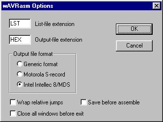
In the box labeled List-file extension the default extension on the list
file(s) is written, and in the box labeled Output-file extension the default
extension of the output file is written. In the box labeled Output file
format the type of format wanted on the output file can be selected. If
the OK button is clicked, the values are remembered in subsequent runs
of the Assembler. Note that the object file (used by the simulator) is
not affected by these options; the extension of the object file is always
OBJ and the format is always the same. If an EEPROM Segment has been defined,
the Assembler also generates an EEPROM initialization file with extension
EEP.
The Wrap relative jumps option tells the Assembler to use wrapping of
addresses. This feature should only be used when assembling for devices
with 4K words of program memory. Using this option on such devices, the
relative jump and call instructions will reach the entire program memory.
The Save before assemble option makes the Assembler automatically save
the contents of the editor before assembling is done.
The Close all windows before exit option will ensure that there are
no windows active the next time the assembler is started.